Hydraulic pressure relief valve diagram Difference between pressure reducing valve and pressure relief valve How does a pressure-compensated flow control valve work?
Pressure-Reducing Valve - Hydraulic Schematic Troubleshooting
Pressure control valve- types , symbol ,application Hydraulic valves : products : valfon valve Mariners repository: hydraulics part 1
Wiring diagram for hydraulic solenoid
Assemble a hydraulic pilot-operated pressure relief valvePressure control: upstream and downstream Hydraulic beginners cylinder electrical fluid fundamentals hydraulik electromechanical acting pnuematic let hidraulica hydraulics drawing pneumatic valves discuss mentionedValve flow pressure control compensated diagram work does fluid path components simplified pressures illustrating within click enlarge.
Hydraulic inline pressure relief valve 150-5000 psi 3/8" up to 1" bsppPressure relief reducing valve symbol hydraulic between difference control hydraulics engineering power upstream downstream symbols circuit easy made pack system Parker prdm3pp06svg10 hydraulic pressure control valve w/d3w4cnjw30 invValve directional control part.
![[DIAGRAM] Pacemaker System Diagram - MYDIAGRAM.ONLINE](https://i2.wp.com/robsonforensic.com/images/uploads/articles/hydraulic-system-diagram-v4.png)
Pressure reducing water valve valves diaphragm type high
Relief hydraulic pressure valve pilot operated fluid power valves assemble journal maximum limit features comments used[diagram] farmall 560 hydraulic pressure relief valve diagram Pressure reducing valve hydraulic schematic control troubleshooting drain valvesPressure relief valve. hydraulic pressure must be regulated in order to.
Types of pressure control valves i pressure relief valve i pressureValves diagrams electro Hydraulic symbology 203 – pressure valvesCircuit simplified piston efficiency valve directional directed.

Valve flow control hydraulic diagram pressure compensated parker operation valves bobcat two 31b permission reprinted hannifin showing figure auxiliary dcv
Hydraulic system for beginners[diagram] pacemaker system diagram Mechanical valves: a device for control flow and pressureHydraulic flow control valves.
Pressure-reducing valveDirectional control valve basics Hydraulic pressure reducing valve symbolPressure reducing valve working video in hydraulic system.

Pressure hydraulic valves circuit symbology relief sequence pump limit
Proportional hydraulic control valves reducing electroHydraulic pressure valve parker control hydraulics npt sku Pressure valve hydraulic control parker invHydraulic control valves.
Hydraulic pressure control valve relief valves qrv series water descriptionBackpressure regulating valve valves pressure back schematic limiting spring loaded illustration inlet plunger side Adjustable pressure control valves for regulating hydraulic pressureParker hydraulics pr6ph hydraulic pressure control valve 1"npt.

Pressure control valves: pressure-reducing valve
Pneumatic actuator pneumatic valve chinaHydraulic pressure reducing valve Valve pressure reducing hydraulic schematic valves troubleshooting controlWay valves two valve spool control three four flow direction drawing pressure rotary port hydraulics ports repository mariners permitting configurations.
Types of pressure control valves i pressure relief valve i, 42% offHydraulic valve control valves directional hydraulics spool basics parts gpm monoblock magister cylinders manufacturer cylinder post flow magisterhyd repair Hydraulic schematic troubleshootingHydraulic pressure control valve.

Reducing hydraulic
Hydraulic reliefSolenoid diverter 12v selector valves hydraulics Flow valves mechanical mechanismSimplified hydraulic circuit schematic for the motor efficiency test.
.


Valves - Pressure Reducing Valves - CTG Technical Blog

Pressure-Reducing Valve - Hydraulic Schematic Troubleshooting
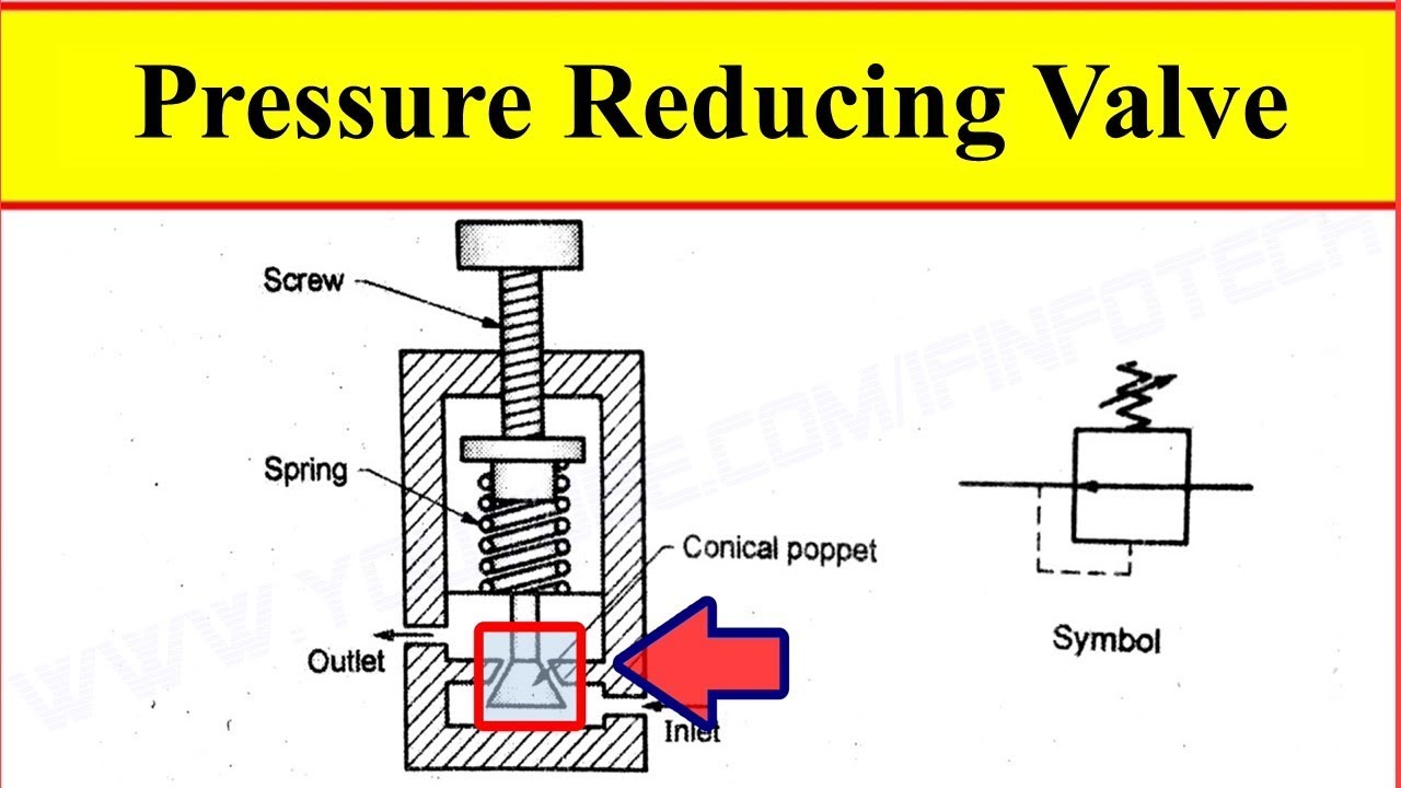
Pressure Reducing Valve Working Video in Hydraulic System - YouTube

Wiring Diagram For Hydraulic Solenoid - Wiring Diagram

DIFFERENCE BETWEEN PRESSURE REDUCING VALVE AND PRESSURE RELIEF VALVE

Hydraulic Inline Pressure Relief Valve 150-5000 Psi 3/8" up to 1" BSPP